I’ve spent a large amount of time working in anechoic chambers, and possibly even longer analysing the data I’ve collected in them. There is something very peaceful about working in a nice quite air-conditioned room with just the background hum of some radio frequency equipment. It almost offsets the problem of the grey colour your hands turn from the carbon in the radar absorbing material. Over the years I was often asked what the anechoic chamber was and why it was used, so here is a quick introduction to all things anechoic chamber.
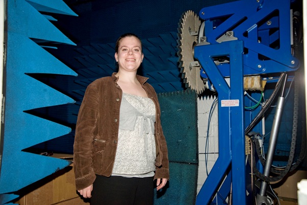
Anechoic chambers are rooms designed to absorb the reflections of electromagnetic radiation and to minimise interfering energy disturbances from external spurious sources. An-echoic means non-reflective, so these are chambers without reflections. Anechoic chambers are used to measure the performance of the antenna under test, in particular gain and pattern characteristics.
Typically, the anechoic chamber wall construction is a Farady cage which prevents external signals entering the anechoic chamber and interfering with measurements. It also prevents test signals escaping from the anechoic chamber, which may interfere with external devices and be a potential health risk. The interior of an anechoic chamber is lined with Radar-Absorbent Material (RAM) with construction and lay-out to provide radio frequency signal absorption across the required frequency band and to produce the quiet zone. The quiet zone is the volume in which the antenna is placed and where the electromagnetic reflections are at a minimum. The reflectivity of the RAM is dependent on the angle of incidence of the radiation. Therefore, the RAM reflectivity needs to be considered when designing the RAM lay out in the anechoic chamber.
The measurement system requires a transmit signal source of radio frequency energy in the correct frequency range and a receive system that is capable of measuring the signal received by the antenna, Vector Network Analyser (VNA). If a low power measurement is to be taken it is possible to use the VNA as the transmit power source and the receive measurement system. The radio frequency transmit signal produced in the VNA can be routed via co-axial cables to a transmit standard gain horn. The signal is then received by the antenna and the receive signal routed to the VNA for measurement via co-axial cables. If a higher power source is needed, additional amplifiers may be required in the radio frequency path before the transmit standard gain horn. Alternatively, the transmit power source could be changed to a solid state power amplifier or travelling-wave tube with additional hardware to ensure phase stabilisation between the transmit power source and the receiving VNA.
A positioning system is required in the anechoic chamber to hold and to move the antenna with respect to the incoming plane wave and hence determine the antennas spatial radiation pattern. The positioning system has the required number of degrees-of-freedom to complete the desired measurements on the antenna. These positioning systems are manufactured from metal and therefore have to be covered in RAM to avoid spurious reflections. There are many possible designs of positioner systems which is dependent on the antenna being measured.
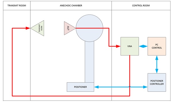
Above is shown a schematic for an anechoic chamber design where the VNA can be used as the transmit power source and the receive measurement system. The site is divided into three sections: transmit room; chamber; control room. The control room contains the control system for the range. The VNA produces the transmitted signal, routed to the transmit horn via a co-axial cable, and analyses the received signal via a co-axial cable attached to the antenna. In the anechoic chamber the positioner holds and orientates the antenna to measure plots in azimuth and elevation and produce full antenna patterns. The transmit room allows the safe transmitting of the amplified VNA signal which can then be received by the AUT on the positioner without exposing users. It has a transmit positioner, which holds the transmit horn, and provides the main lighting for the chamber.
Anechoic chambers are used for convenience over open air ranges. Taking measurements in an anechoic chamber is logistically easier than an outdoor range as the site is smaller, contained within an existing building with amenities and its functionality is independent of weather. In addition, it is easier to measure the antenna’s phase with respect to the reference signal as the distances involved are smaller. The anechoic chamber also helps to minimise the health and safety impact of working with high power radio frequency radiation as transmissions are contained.
However, because anechoic chambers simulate an outdoor range and can only minimise spurious radio frequency reflections, the performance of the anechoic chamber has to be properly assessed. Range effects, such as spurious reflections, can be identified by measuring the antenna at different rotational orientations, antenna effects are reflection features in the pattern that rotate with the antenna, range effects stay in the same location.