Feed horns have always held a fascination for me, just make a bit of shaped metal and you can control electromagnetic radiation. In my opinion, a great super power to have! However, when you put several feed horns together you can create something even more powerful and informative.
A feed horn is a type of horn antenna, which means it is formed by flaring the sides of metal waveguide into a horn like shape thus creating a controlled beam of radio waves. A feed horn is often used as the feed in reflector antennas. It transmits the electromagnetic signal between the transmitter or receiver and the reflector, so is placed at the focus of the reflecting part of the system. Depending on design it can also select the polarisation of the incoming electromagnetic wave, which helps remove unwanted signals. The feed horn can be air or resin filled to control the electromagnetic radiation. A feed horn can work in both transmit and receive modes, as passive antennas are reciprocal.
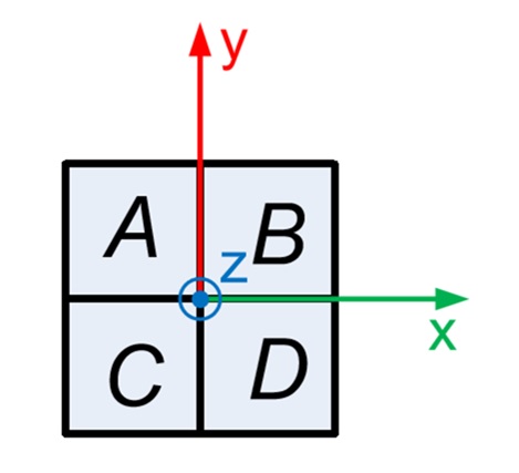
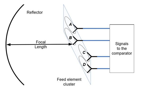
A monopulse system is one that sends out multiple overlapping beams at the same time. Typically, a monopulse antenna is an antenna array which is symmetrical about boresight. In the case of a monopulse feed horn it is normally constructed from four feed elements: A, B, C, D. These feed horns are fed the transmit signal, and they radiate into space four slightly overlapping beams, then receive four separate reflected signals. Typically, for an amplitude-comparison monopulse antenna system, there is a focusing element in front of the feed horn at the focal length. In this example the focusing element is a parabolic reflector, but a lens can be used as well.
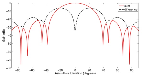
From the overlapping beams produced by the feed elements the Sum (Sigma) and Difference (Delta) signals can be calculated in Azimuth and Elevation, and the signal analysed by the receiver attached to the feed horn. Sum maximises the signal at the centre of the antenna beam, and is where all four beams overlap. Delta produces a null at the centre of the antenna beam and has an amplitude related to the angular distance between the object and boresight in Azimuth and Elevation. A difference at 45 degrees to the Azimuth and Elevation axes can be created (Q), which may be used to help detect jamming signals or improve angular estimates, but is not of significant use and is typically terminated and unused in waveguide based comparator systems. Examples of a simulated Sum and Difference signal can be seen below.
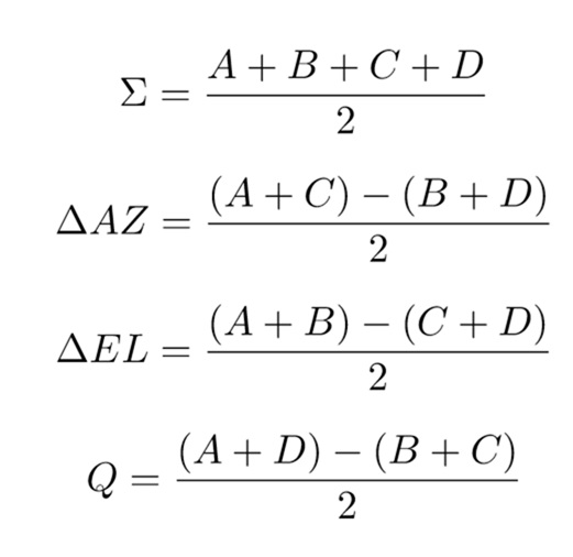
The Sum and Difference signals can be formed by using a hardware comparator. This is a device that connects to the feed elements and forms linear combinations of the signals received by each feed element to produce Sum and Difference as shown in the equations below. A comparator is a collection of dividers and combiners; the exact choice of each item is dependent on the requirements for the system. It is important that no phase or amplitude errors are introduced by the comparator, so the four ports need to be highly symmetrical and the phase shift introduced by the symmetry requirements taken into account. Comparators can be made from waveguide or stripline, but in tracking radars the high power requirements means they are made from waveguide. Comparators have the advantage of being passive, reciprocal and stable, however they are spatially large, expensive to manufacture, have high mass and introduce signal loss to the system. The function of the combiner can be thought of as shown in the equations below:
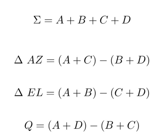
The signals can also be formed in software if the additional computational power is available and four receivers can be introduced into the system, thus removing the need for the comparator, by using the following equations:
Monopulse antenna systems are a common choice in tracking applications as it allows the calculation of range and direction from a single pulse. In single beam antenna systems at least 3 different beams would have to be sent and received to get accurate positioning, each sent at a slightly angle. Other uses of monopulse antennas include reflector antenna systems, satellite communications, radio astronomy and sonar.
Advantages of monopulse systems over a single antenna include:
- Accurate Azimuth and Elevation target position estimation in one transmission
- The ability to detect jamming which makes it a very popular choice for tracking radar
Disadvantages include:
- More complicated design
- Larger footprint and mass if a hardware comparator is used
- Higher manufacturing cost
Monopulse beams are not limited to just 4 feed horns and can be formed from large arrays containing up to many hundreds of elements with Sum and Difference signals being formed. However, there are many differences between a four port monopulse feed plus reflector antenna and an array being used to produce monopulse signals. In larger systems the antennas are often Active Electronically Steered Arrays (AESA) or slot antennas which behave very differently to a reflector antenna. In a four port monopulse antenna in a reflector system beam steering and shaping, power synthesis and power taper are not implemented as they are not required.