The word radome is a portmanteau of the words radar and domes, they are designed to cover an antenna and protect it from the elements. Growing up near the golf balls in the North York Moors I have known about radomes for a long time, and always found them fascinating. I was really happy that one of the first jobs I had when I started in engineering was to ‘just look after’ the design and manufacture of a new radome. It was supposed to be just a part time occupation for a few weeks. However, it turned into a full-time job of several years to get a good radome design that could be repeatably manufactured and worked well with my antenna. In this blog I am going to look at different types of radome shape, material and thickness.
WHAT IS A RADOME
For an antenna to successfully operate environmental protection is often required. Radomes are structures that cover an antenna providing this environmental protection whilst, by design having limited effect on the performance of the antenna. The external profile, robustness and material of the radome vary greatly depending on its purpose.
The introduction of a radome to an antenna system has an effect on the performance of the antenna. It will increase transmission and receive losses, distort the pattern and polarisation of the antenna pattern and cause errors in boresight measurements. The radome will cause a refraction of the electromagnetic signal being detected by the antenna, resulting in an apparent movement of the source, aberration. If the radome is too close to the antenna it will interact with the near field of the antenna causing a new range of problems in the antenna pattern.
RADOME SHAPE
External profiles of radomes range from hemispherical and geodesic through ogive and conical to the very pointed Von Karman profiles depending on the purpose of the antenna.
If the antenna is land based, then a more radio frequency performance friendly hemisphere can be used. However, if the antenna system is for aerospace purposes then the radome will become more pointed to aid aerodynamics.
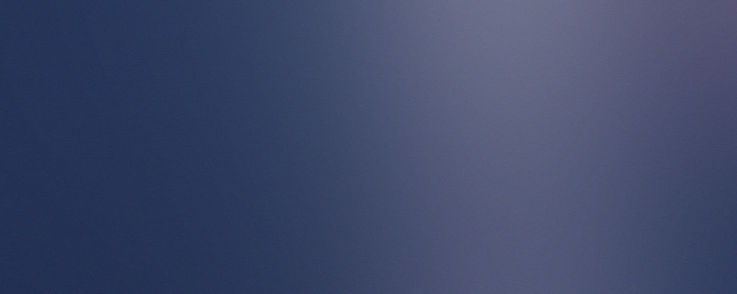
The best shape for a radome is a hemisphere a good distance from the antenna. This has minimum impact on the antenna pattern as the same disturbance is seen over the entire field of view. Making large spheres is often quite difficult. So instead geodesic domes are often used, like the ‘golf ball’ radomes seen at the Royal Air Force Fylindales that were part of the ballistic missile early warning system. By 1992 these domes had been replaced by an AESA phased array tetrahedron structure, but are still locally referred to as the golf balls. As long as these radomes are carefully designed the antenna will ‘see’ the geodesic dome as a hemisphere and not the individual sections.
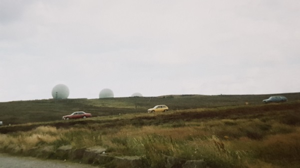
If the antenna is to fly then the radome has to be an aerodynamic shape such as an ogive, conical or Von Karman, meaning the refraction caused by the radome changes as a function of scan angle of the antenna. This aberration has to be compensated for during measurement of the target which has to be measured over all scan angles.
RADOME MATERIAL AND STRUCTURE
The material choice is a compromise between radio frequency and mechanical performance. The radome has to be as transparent as possible to radio frequencies, but strong enough to cope with the environmental conditions that the antenna will be exposed to. As radomes are often mounted in aerospace systems they have to be able to withstand the launch stresses and the environmental heating. Ceramic and composite materials are common choices for radomes in these situations.
Radomes can be made from a single electrically thin dielectric layer or a sandwich, which has two dielectric layers with an alternative material between them as a core at its simplest.
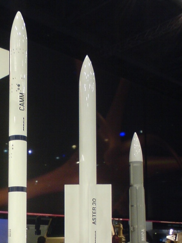
Larger radomes can be made in sections, like the golf balls, as the discontinuities cause little problem to the antenna. For smaller radomes who have to withstand flight they are made as a monolith, like the missile and plane radomes, to ensure safety.
RADOME THICKNESS
However radomes are constructed their thickness has to be carefully tuned to be a matched thickness for the frequency of electromagnetic radiation being used.
Traditional methods of designing radome thicknesses are time consuming and expensive, often requiring iterations of hardware manufacture. These are based around complex equation approximations, ray tracing or electrically large electromagnetic simulations to find the matched thickness.
IN SUMMARY
This has been a brief introduction to radomes, their shape, construction and importance to antennas. Radomes are really interesting things to design and test as they use a lot of different skills and processes. It is really exciting to see a radome you have designed out in the wild!