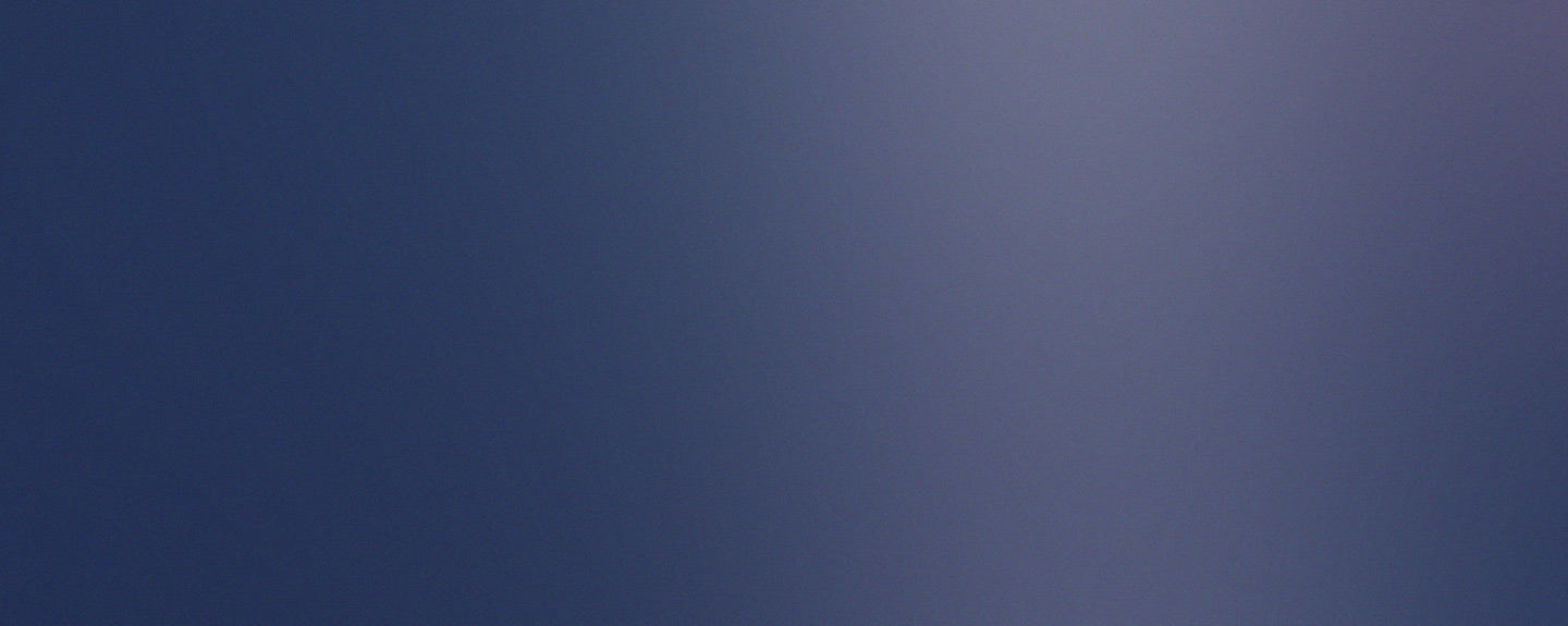
So, this weekend was a perfectly normal weekend at the home of Swamphen Enterprises. It was one of those weekends spent sorting out all those things in the house you never quite get round to doing. One of these was deal with the satellite dish that the previous owner had left attached to the wall, but with the cable cut. This satellite dish has been acting as a decoration for the last 10 or so years, and it was time for this to end. You will be familiar with this dish, as it starred as one of my blog post about how a perforated dish can act as a solid piece of metal. Having removed it from its long-held position, it was only fair to do a teardown of it!
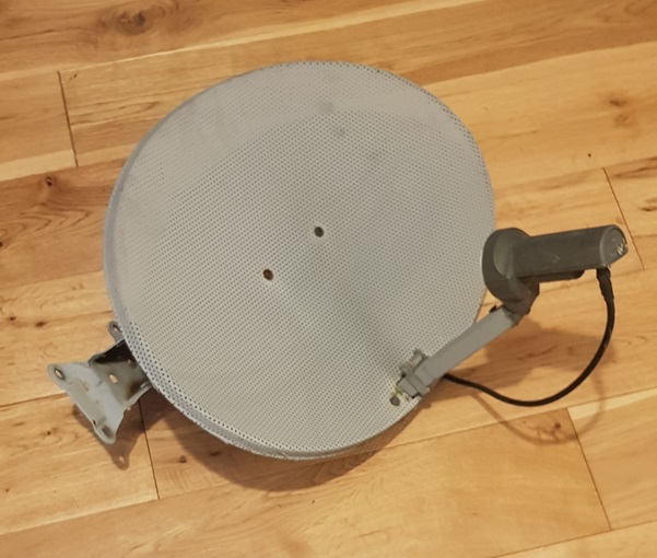
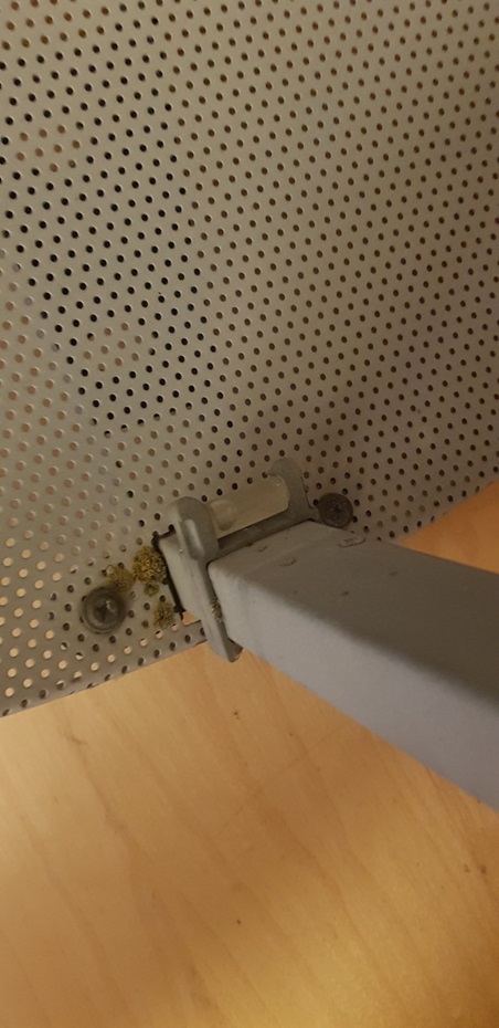
We will start with the attachment to the wall. There were four serious bolts holding the antenna to the wall, not that this is surprising as there would have been a lot of movement induced in the reflector from the wind. If you were designing a mounting system you wouldn’t want your dish to miss-align easily and ruin your TV reception.
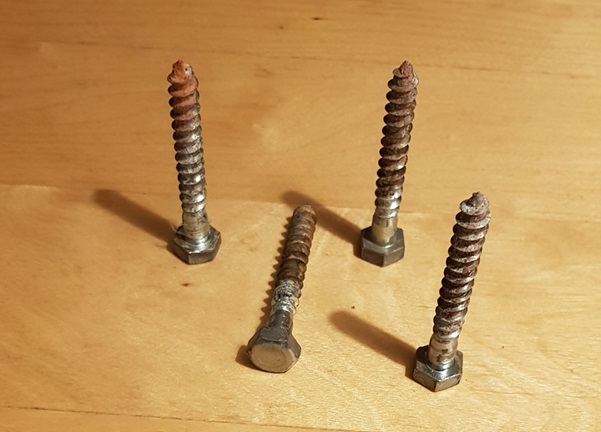
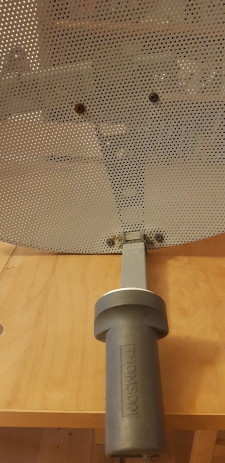
Attached to the back of the reflector is a mounting system. This is a double axis mount allowing for movement in azimuth (horizontal) and elevation (vertical) so the dish can be properly lined up to point at the satellite after installation. Again, this is great for getting a perfect TV signal and means the installer has some ability to align the dish after the large mounting holes have been drilled into the brick.
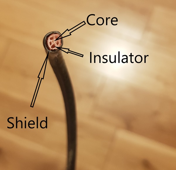
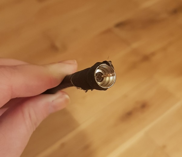
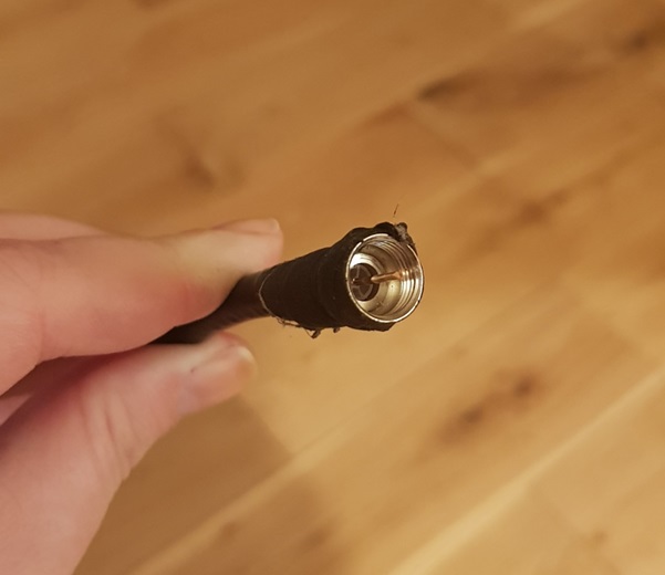
Along with the actual satellite dish we also removed many meters of co-axial cable that snaked around the house from the dish to the entry point near the back door. This turned out to be pretty standard co-axial cable, a transmission line, used to carry the electromagnetic signal received with low losses and signal interference. In this picture you can see the metal conducting core, the plastic insulating layer and the surrounding conducting shield. This cable went from the back of the receiver on the reflector antenna taking the received signal straight to your set top box connected to your TV.
The dish itself is really interesting on closer inspection. The holes in the paraboloid part of the dish can be clearly seen and seem to be well finished on both sides of the dish. The ‘edge’ of the dish is formed by just bending the metal round into the required shape, but the actual edge is just unfinished cut metal. If this dish were designed to detect different frequencies, or a weaker signal, then the edge of the dish would have to be carefully designed and manufactured.
There are two large screws near the centre of the dish, which will definitely cause a disturbance with this part of the reflected signal. However, the disturbance will be small enough that it does not stop the dish from meeting the required specification, and the screws will make it a lot easier to assemble the system. A good example of pragmatism in design. Sometimes a design is too difficult to manufacture or install, so compromises have to be made. As long as the total sum of these compromises can be tolerated, then this is a very sensible approach. This means other details will have to be well specified, manufactured and installed, but hopefully these will be easier details to do this with.
At the front of the dish on the receiver arm there is a little spirit level that is used during set up to ensure the receiver is parallel with horizontal. This will ensure the co and cross polar signals are correctly aligned, and therefore signal is not lost. Putting the spirit level in situ will make this an easier task for the installer, and the correct alignment have a big impact on the amount of signal received which will offset issues with the screws in the dish.
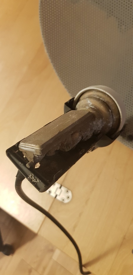
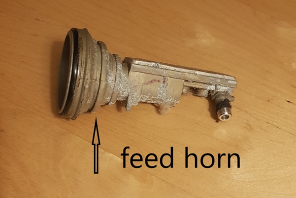
The receiver, a low-noise block downconverter (LNB), sits on the end of the receiver arm which is at the focus of the parabolid of the reflector. In this picture the receiver is more clearly seen as the top of the plastic housing has been removed. You can see the cast metal housing of the receiver electronics, where this flares to make the feed horn, and the plastic radome on the top of the feed horn.
I would like to add an apology for the large number of spiders I evicted from their home for the sake of science. I can only sympathise with satellite dish installers as to the number of spiders they must encounter on a daily basis.
SATELLITE DISH FEED HORN TEAR DOWN
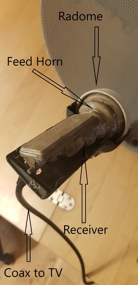
This is a close up of the feed horn and receiver that is at the focal point of the paraboloid of the offset fed parabolic reflector satellite dish. It takes the electromagnetic signal collected by the dish, converts the free space electromagnetic signal to an electric current to be processed in the circuit board of the receiver and transmits the signal to your TV set.
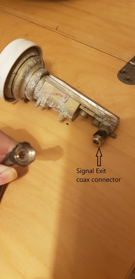
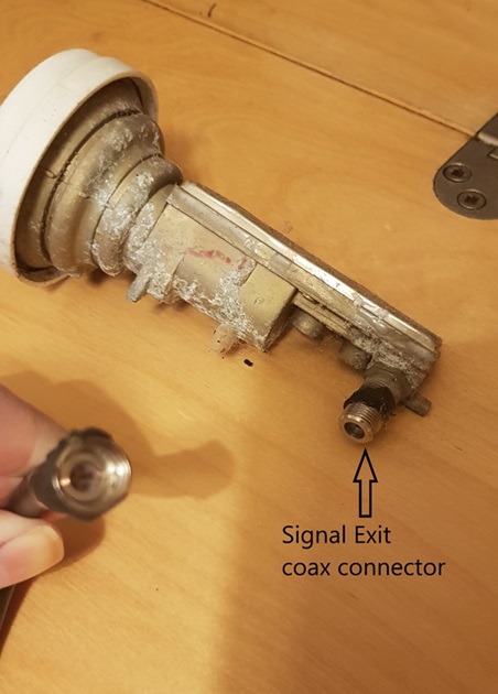
Having removed the feed and receiver unit from the feed arm you can see that the final processed signal comes out at the back of the feed unit. A male SMA cable connects to a standard coax cable, which is then routed into your house.
The next piece to be removed was the radome, which is made of plastic and was snap fitted very tightly over the end of the feed horn. This will stop any moisture or insects getting into the feedhorn. If I have learnt anything working on outdoor test sites, it is that spiders love to make their homes in feed horns. Secondly, that the smell of roasted spider is not something you want to be inhaling. It is interesting to note that the radome is slightly convex, so that there is the same distance from the radome to the back of the feed horn for each of the rays, which minimises the impact of the radome on the signal. Also included in this photo are some cobwebs from the re-homed spiders for authenticity and showing that they didn’t make it inside the feed horn.

The radome is made from injection moulded plastic, the injection point can be clearly seen in the centre of the radome. This will cause some perturbation in the signal, but this will be at a low level and be acceptable to the overall system. Injection moulding is a common process for mass produced parts and to remove the injection point, so the final radome is a constant thickness all the way across, will make the part more expensive to produce with a small improvement in performance.

Looking at the exposed feed horn there are several features immediately apparent. The sides are sloped, there are ridges on the inside of the feed horn, and metal rods sticking into the space in the middle. The feed horn seems to be made from metal casting as it has some small defects that can be seen at the end of the feed horn. It is probably lost wax casting, as there are some holes that go all the way through the casting which do not appear to be post machined. Metal casting is a common choice for mass production metal parts and is extensively used for waveguide parts.
The sloped sides flare the circular wavegude (the cylindrical part with a fixed diameter at the back of the feed horn) into a feed horn. This flaring is used to match the impedance of wave in the wave guide to the impedance of free space. Therefore, using a feed horn allows the electromagnetic energy to radiate out into space with minimal disturbances and reflections.
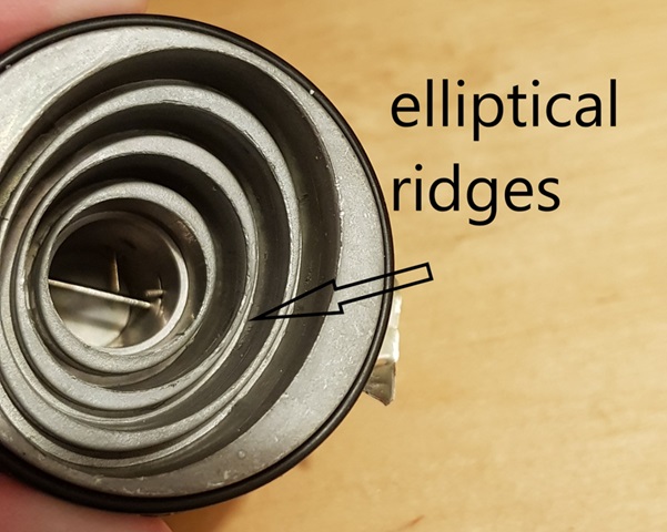
The feed horn itself is a corrugated elliptical feed horn. The outside of the horn looks conical, but the elliptical shape is formed on the inside. This feed horn is elliptical to match the shape of the reflector dish it is paired with, reducing issues like spill over.
Making the x axis of the reflector dish larger that the y axis means you have a reflector with the properties of the size of the x axis (in particular reducing interference from adjacent satellites), but the overall size has been reduced by reducing the y axis (making it more aesthetically pleasing). So, by reducing just the size of one of the axes the beam width stays the same, but the overall gain reduces (as you have less collecting area). This is fine if you live in the South of England as the signal strength from the Astra 2 cluster is high here, but less great if you live back in Yorkshire or further north where the signal strength could really do with that extra bit of collecting area.
The ridges on the inside of the feed horn allow the feed horn to operate over a wider range of frequencies, reduce the size of the side lobes of the signal and allows the feed horn to work in two polarisations.
In the section of circular waveguide at the back of the feed horn there are two waveguide to coax transitions at the back at 90 degrees to each other, the small metal pins sticking into the waveguide hole that go halfway into the space, at right angles to each other. These are right-angled coax to waveguide transitions, which are commonly used as they have a low VSWR. A current is induced in these ‘mini monopole antennas’ which takes the signal from the waveguide to the circuit board receiver.
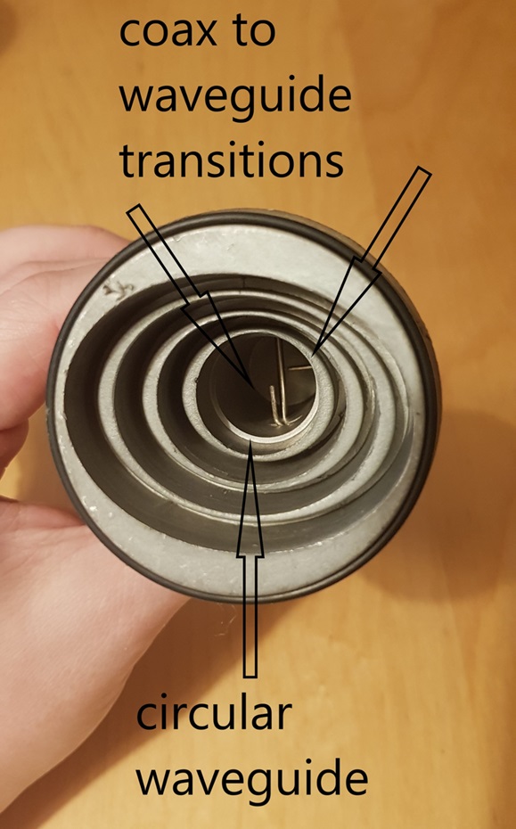
The metal rod going the entire distance across the waveguide is interesting. It is not part of the coax to waveguide transitions, as the metal rod does not go to the circuit board. It is also not part of the original build, as it has been added in after the casting and is of the same quality metal as the antennas in the coax to waveguide transitions. I’m not sure what this is for, and have not been able to confirm its purpose in the literature. It is located further back than the two transitions and at a different angle, I think it is to stop cross talk between the two polarisations of the coax to waveguide transitions. If you know, then please tell me in the comments!
If you want to see the electronics inside the receiver, then tune in next week as I will be cutting my way into them then.
SATELLITE DISH RECEIVER TEARDOWN
The receiver, a low-noise block downconverter (LNB), sits on the end of the receiver arm which is at the focus of the parabolid of the reflector. In this picture the receiver is more clearly seen as the top of the plastic housing has been removed. You can see the cast metal housing of the receiver electronics, where this flares to make the feed horn, and the plastic radome on the top of the feed horn.

This is a close up of the feed horn and receiver that is at the focal point of the paraboloid of the offset fed parabolic reflector satellite dish. It takes the electromagnetic signal collected by the dish, converts the free space electromagnetic signal to an electric current to be processed in the circuit board of the receiver and transmits the signal to your TV set.
Having removed the feed and receiver unit from the feed arm you can see that the final processed signal comes out at the back of the feed unit. A male SMA cable connects to a standard coax cable, which is then routed into your house.
The next piece to be removed was the radome, which is made of plastic and was snap fitted very tightly over the end of the feed horn. This will stop any moisture or insects getting into the feedhorn. If I have learnt anything working on outdoor test sites, it is that spiders love to make their homes in feed horns. Secondly, that the smell of roasted spider is not something you want to be inhaling. It is interesting to note that the radome is slightly convex, so that there is the same distance from the radome to the back of the feed horn for each of the rays, which minimises the impact of the radome on the signal. Also included in this photo are some cobwebs from the re-homed spiders for authenticity and showing that they didn’t make it inside the feed horn.
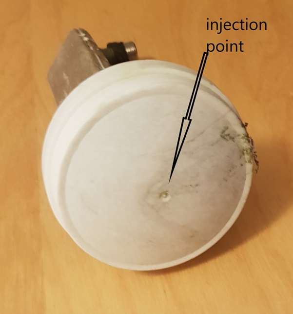
The radome is made from injection moulded plastic, the injection point can be clearly seen in the centre of the radome. This will cause some perturbation in the signal, but this will be at a low level and be acceptable to the overall system. Injection moulding is a common process for mass produced parts and to remove the injection point, so the final radome is a constant thickness all the way across, will make the part more expensive to produce with a small improvement in performance.
Looking at the exposed feed horn there are several features immediately apparent. The sides are sloped, there are ridges on the inside of the feed horn, and metal rods sticking into the space in the middle. The feed horn seems to be made from metal casting as it has some small defects that can be seen at the end of the feed horn. It is probably lost wax casting, as there are some holes that go all the way through the casting which do not appear to be post machined. Metal casting is a common choice for mass production metal parts and is extensively used for waveguide parts.
The sloped sides flare the circular waveguide (the cylindrical part with a fixed diameter at the back of the feed horn) into a feed horn. This flaring is used to match the impedance of wave in the wave guide to the impedance of free space. Therefore, using a feed horn allows the electromagnetic energy to radiate out into space with minimal disturbances and reflections.

The feed horn itself is a corrugated elliptical feed horn. The outside of the horn looks conical, but the elliptical shape is formed on the inside. This feed horn is elliptical to match the shape of the reflector dish it is paired with, reducing issues like spill over.
Making the x axis of the reflector dish larger that the y axis means you have a reflector with the properties of the size of the x axis (in particular reducing interference from adjacent satellites), but the overall size has been reduced by reducing the y axis (making it more aesthetically pleasing). So, by reducing just the size of one of the axes the beam width stays the same, but the overall gain reduces (as you have less collecting area). This is fine if you live in the South of England as the signal strength from the Astra 2 cluster is high here, but less great if you live back in Yorkshire or further north where the signal strength could really do with that extra bit of collecting area.
The ridges on the inside of the feed horn allow the feed horn to operate over a wider range of frequencies, reduce the size of the side lobes of the signal and allows the feed horn to work in two polarisations.
In the section of circular waveguide at the back of the feed horn there are two waveguide to coax transitions at the back at 90 degrees to each other, the small metal pins sticking into the waveguide hole that go halfway into the space, at right angles to each other. These are right-angled coax to waveguide transitions, which are commonly used as they have a low VSWR. A current is induced in these ‘mini monopole antennas’ which takes the signal from the waveguide to the circuit board receiver.

The metal rod going the entire distance across the waveguide is interesting. It is not part of the coax to waveguide transitions, as the metal rod does not go to the circuit board. It is also not part of the original build, as it has been added in after the casting and is of the same quality metal as the antennas in the coax to waveguide transitions. I’m not sure what this is for, and have not been able to confirm its purpose in the literature. It is located further back than the two transitions and at a different angle, I think it is to stop cross talk between the two polarisations of the coax to waveguide transitions. If you know, then please tell me in the comments!